This when i was checking the relay wiring dragram
Name of the relay or switch that power up the ABS ECU is Ignition Switch
Name of the relay or switch that powers up the ABS ECu pump is ABS motor relay
NAme of the relay or swtch that sens pwoer to the ABS Hcu soleniods is Fail Safe Relay
Relay wire Identifications
what is the ECU pin number for the wire that brings in the pwoer to the ABS ECU?
11F
what is the ECU pin number or other number, for the wire that controls the relay for the ABS ECU is 2h
What is the pin number for the wire that brings in the power to the ABS Pump
1L
what is the pin number or other number, for the wire that controls the relay for the ABS Pump?
2H
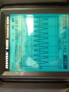
Relay Waveform

you can see 2 patterms in 1 waveform so it two triggers. startin is Relay off then goes 12 voltgs then relay on then supply the wirings switches to the ABS pump motor to the speed sensor then goes to earth. the bottom one is EMF supplyin through the big firing then swtch the relay on then goes to grounds.
A the top part is the a relay siwtch when the ecu grouds a point of the relay and there a quick voltage drop.
ABS Pump Relay Waveform
This waveform shows that the voltage has induced arocess the coil of the relay
so when it switchted there is a somthing i dont know wt u called it . but the current to pass it by switching.
ABS self test
when you the pwer on the orange warning light turns on for a few seconds after that i looked at the oscilloscape and it was showing like analgoe waveform and you can see the power supply on the postive side of the ABS system
A faults
when the breake system applied it force on one wheel sensors then the ABS activited on the pressure the pedal goes hard when the ABS is on and realse the speeds the vibration that i feel in the pedal which it could tell me the ABS was working and it ws releasing and increasing pressure in the certian times.
ABS soleniod
the pin number is 01- 04 RR mean right rear by looking wiring dagiam of the ABS system.

you can see the solenoiods is switched and then voltages climbbes up slowly pointin on the top becausie it going really faster n the voltages open to open it. and when the brake pedeal is released it striaght away then closed and carry on the earth in the ABS ECU points.
On Vehicle Testing
identify the componets
 found all the component in the car the hard part i was loookin for the RPM sendsor and Mian ABS control unit fuse/
testing ABS Wheel Speed Sensor
it analogue the reason i found it because it was showing a anaglue waveform from wheel speed sensors.
Nw measuring the air gap and the visual condition of each wheel sensors
Front right good conidtion a few grease stand on the side of the teeth plate but nothing mayor to afffect the singal the gap is 0.022m
Front left , good condtion the gap is 0.024m
Rear Right unable to see as located in the brake drum the gap is 0.023m
Rear Left unable to see as located in the brake drum the gap is 0.024m
Wheel sesnor waveform
 this pattern is analogue
11 time per a second and the volts is 1.17v that how the speed sensors work when you spining the tyre. the more faster u spin the analogues moves up and down quickly, you can see the differnt betweeen slow and fast.
Using a Scan tools
finding all the sensors using the sccan tools
- ABS VAULVE CONTROL RELAY
- ABS WARNING LAMP STATUS
- BATTERY POSTIVE VOLTAGES
- LF ABS IN VALVE
- LF WHEEL SPEED SENSOR
- RR ABS OUT VALVE
- HYDRAULIC PUMP MOTOR
- BRAKE WARNING LAMP
- BRAKE SWITCH
Using a scan tool and click on actuator test screen On nissian aveniv
3 stages seloiends
keep - hold the postion
down- down pressure
up- presssure increased
on building up pressure is
FR RH SOINOIDS
FR LH SOLEINDS
RR RH SOLEONDS
RR RL SOLEINOIDS
when your into soleenoids test mode on the muiltcan you can go to each other solenoid and push eneter then liite screen thing comes up and press it 1 to tuirn the on and 2 to turn off the hold solenoid should click like a smal vibrate . in hold postion the inlet and outlet wil be both closed
Electronics Tranmission and Scan Tools
Abbreviations
PCM- powertrain control module
TCC- torgure converter clutch
TPS- throttle postion sensors
ECT-Engine coolant temperature sensors
VSS- vehicle speed sensors
PSA- Pressure Switch Assembly
TTS-Transmission Temperature Sensors
BLOCK Diagram from HOlden manuuel book
Sensors
gear selection switch
encomory/power sitch
Throttle postion sensors
vehicel seepd sensor
air condidtion switch
engine speed sensors
tranmission
temperature sensor
Powerstrian Control Module
shift patterns
shift duartions
adaptive controls
extreme heat protections
Actuators
shift solenoids
pressure control select
torqure conster clutch solenoids
Diagnostic
Wiring diagram
Mitsubishi Galant 1996
Air condition Heater
 you can see a motor blower in the daigaim and the fuse but there two fuses they are 30a and other is one is 10a and there is a relay was. the big squre has a blow siwtch and addjustble that you turn the temperature low or high.. there two ground black wires bt im surwe there is a way to connect the battery to the cicuit but somewhere.
Using a holden Shift Chart
Shift soleniods
first gears is 1-2 and 2-3
second gear is 2-3
third both of them are off
fourth gear 1-2
the car would be stuck in the 3rd and it would nt change but the car could stil drive but it would have a a very slow take off like start driving and i dont think it would have the power to drive up to the hill . maybe would have to depend on the how high is the hill. the power from the engine and the speed you like how mch pressure you put on the pedal and the grear shift of the gear box could also make a difference.
CODES
Code 14
Engine Coolant temperature (ECT) sing voltage low
Code 21 Throttle Position Sensor singal voltages high
Daignosis
code 14
the problem could be the siginsl voltage been above 140c. well use a scan tool and display eingne coolant temperture of 140 c or higher. disconnect the wiring harnesss temperature sensors and then the scan tools should display like showing the engine coolant temperature below 30c if it does then need to be replace a engine coolant sensors
code 21
if the throttle closed then use a scan tools data and if it over 1.25 volts then disconnect the wiring harness from the throttle pistion sensors. then use the scan tools and check if the TPS below 0.2 volts then try probe the TPS then use a tester light and see if it on. if it on then there is a faults connections or faulty TPS sensors.
ON Car exerise
scan tool is Multscan
honda commodere
First gear 1-2 on 2-3 on
second gear 1 -2 off 2-3 on
third gear off off
fourth gear 1-2 on 2-3 off
Torgue conveter clutch on
it is on only the forth gear and in the third gear at high revs so it lock up by itself
Torgue conveter clutch off
it is off in the first and second and third gears and reverse and park
it goes on into forth gear all the time in the third gear at high as soon as the brake was touch it and it quickly turned off.
this is a base of shitfing gears


 this is a right indicator you can see the wavform flowing .The starting is of the height is long and the width is short atfer two of thoses then it goes from hieght long and width long.


